-
Notifications
You must be signed in to change notification settings - Fork 427
WM230 Main Core Processor board
Function
Variants
Parts
Programming
External interfaces
Service interfaces
Board view
Schematics
The board stores most of computational power of the drone. It contains video encoder for both FPV and SD-card, but also video recognition for positioning (VPS) and gesture control. It also contains transceiver and high-frequency components. And to top that, the gimbal arms control is on this board too.
Several versions of the module are known.
| Marking | Overview |
|---|---|
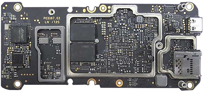
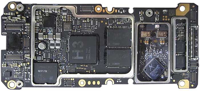
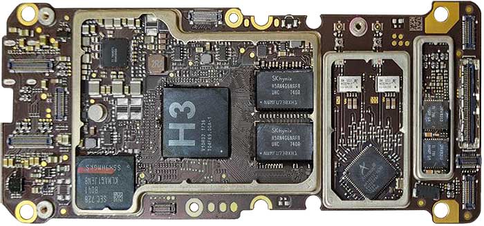
| P03067.03 | The first version. |
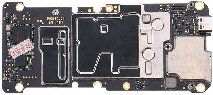
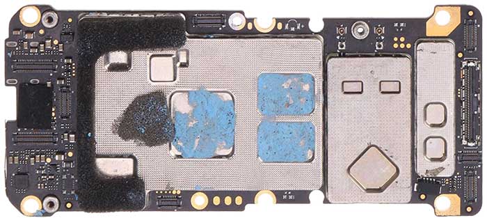
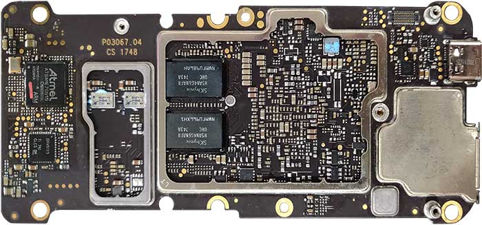
| P03067.04 |
Size of the board, measured at envelope (outermost points), is 112.6 x 49.2 mm.
| Marking | Amt. | Pkg. | Function | Specification |
|---|---|---|---|---|
| H3 V10R02 1736 T04F69.00A-1 | 1 | FBGA | H3 "Eagle", Custom ASIC based Imagination Technologies IP, Cortex-A7 CPU, PowerVR e5500 encoder, TrustZone | |
| DRV8313 TI 781 AHQP G4 | 3 | 2.5A Three Phase Brushless DC Motor Driver (PWM Ctrl) | description | |
| SKhynix H5AN4G6NAFR UHC 740A NWMFU730XH1 | 2 | 4Gb CMOS Double Data Rate IV (DDR4-2400) Synchronous DRAM | datasheet | |
| 85743-11 614653S4 1725 MX Sky | 2 | Front-End Module, 5.5 to 5.925 GHz, 32 dB, WLAN, 24-Pin, LGA, 802.11ax | description | |
| Atheros AR1021X-CL3D FU72929F 1729 CHINA | 1 | QFN | IEEE 802.11a/b/g/n 2.4 to 5.8GHz 2T2R WiFi SoC with internal PA and LNA | related spec |
| TI 79C8D7I 65961B3D0 | 1 | Power Management Unit (PMU) for Processor | ||
| SEC 728 B041 KLMAG1JENB S5X9HMGKS | 1 | 153FBGA 11.5x13 | Samsung KLMAG1JENB-B041 eMMC 128Gbit, eMMC5.1 | description |
| CAXMHY | 1 | |||
| DF8 | 1 | |||
| Atmel ATSAME70N10 3N 1735C A AFN4KA ARM | 1 | ARM Cortex-M7 CPU; up to 300MHz, 16Kb ICache and DCache with ECC, Single- and double-precision FPU, Memory Protection Unit, DSP and Thumb-2 Instructions | description | |
| 85331-11 293042.1 1737 MX Sky | 2 | Front-End Module, 2.4 GHz High-Power 802.11ax WLAN | description | |
| SKhynix H5AN4G6NAFR UHC 743A NWMFU986AH | 2 | 4Gb CMOS Double Data Rate IV (DDR4) Synchronous DRAM | datasheet | |
| VE J | 3 | |||
| 4R 79 | 1 |
| Chips | Firmware | Description |
|---|---|---|
| H3 Eagle | m0801 | |
| ATSAME70 | m0400 | Gimbal master control; provides gimbal arm microcontrollers with proper signals to ensure stabilization and responsiveness to user commands. |
| AR1021X | Wi-Fi transmission. |
| Marking | Overview |
|---|---|
| TODO |
The following service pads exist on this board:
| Marking | Overview |
|---|---|
| TODO |
Top of a P03067.03 board:
Bottom of the P03067.03 board:
Top of a P03067.04 board:
Bottom of the P03067.04 board:
Top of another P03067.04 board:
Bottom of the P03067.04 board:
flowchart LR
    Gimbal-FFC-cable((FFC to<br/>Gimbal))
    Gimbal-FFC-cable== image<br/>sensor<br/>data ====Processing-SoC
    subgraph Main Core Processor board
    Processing-SoC[H3 Eagle SoC<br/>Cortex-A7<br/>PowerVR e5500<br/>FC within TZ]
    Processing-SoC== high bit rate<br/>video & photo ===Media-SD-Slot(SD-card slot)
    Processing-SoC== low bit rate<br/>video stream ===Wifi-Transceiver
    Processing-SoC-- DUML<br/>packets ---Wifi-Transceiver
    Media-SD-Card[SD-card]
    Media-SD-Slot---Media-SD-Card
    subgraph Wifi transceiver block
    Wifi-Transceiver[AR1021X<br/>802.11A/N<br/>dual-band<br/>WiFi Module]
    Wifi-Transceiver===RF-Frontend-A1[SKY85331-11<br/>WLAN 2.4GHz<br/>front-end]
    Wifi-Transceiver===RF-Frontend-A2[SKY85743-11<br/>WLAN 5.8GHz<br/>front-end]
    Wifi-Transceiver===RF-Frontend-B1[SKY85331-11<br/>WLAN 2.4GHz<br/>front-end]
    Wifi-Transceiver===RF-Frontend-B2[SKY85743-11<br/>WLAN 5.8GHz<br/>front-end]
    RF-Switch-A[RF<br/>splitter]
    RF-Switch-B[RF<br/>splitter]
    RF-Frontend-A1===RF-Switch-A
    RF-Frontend-A2===RF-Switch-A
    RF-Frontend-B1===RF-Switch-B
    RF-Frontend-B2===RF-Switch-B
    end
    end
    Antenna-A1((Ant))
    Antenna-B1((Ant))
    RF-Switch-A===Antenna-A1
    RF-Switch-B===Antenna-B1
Thick lines present propagation of video data. The video comes from sensor board through Flex Film Cable. The sensor data goes to H3 Eagle, which is the central SoC for main camera video data processing. It applies proper filtering to the data, then generates two streams out of it - high bandwidth stream is H.274/MPEG-4 compressed and written to SD-card (if recording), low bandwidth stream is sent to AR1021X Wifi chip for radio transmission to the RC. The Radio Frequency channels includes separate 2.4GHz and 5.8GHz front-ends, allowing transmission through both bands.
The antennas can also receive DUML packets from the RC, in which case the input RF signal is amplified through RF frontend and received through AR1021X. The DUML packets are then routed to other modules of the drone.
flowchart LR
    Gimbal-FFC-cable((FFC to<br/>Gimbal))
    Gimbal-FFC-cable== image<br/>sensor<br/>data ===Processing-SoC
    FFC-IMU((FFC<br/>to IMU))
    FFC-Sensors-Front((FFC<br/>to Front<br/>Cameras))
    FFC-Sensors-Back-Down((FFC<br/>to Back<br/>and Down<br/>Sensors))
    FFC-IMU---Processing-SoC
    FFC-Sensors-Front---Processing-SoC
    FFC-Sensors-Back-Down---Processing-SoC
    subgraph Main Core Processor board
    Processing-SoC[H3 Eagle SoC<br/>Cortex-A7<br/>PowerVR e5500<br/>FC within TZ]
    Processing-SoC---Processing-RAM[4x 4GB<br/>DDR4-2400]
    Processing-SoC---Processing-EMMC[16GB<br/>eMMC]
    Processing-Xlat(quartz<br/>oscillator)
    Processing-SoC---Processing-Xlat
    end
The Intelligent Flight Functions diagram is much simplified compared to previous drones, as many functions which were previously performed by separate chips have been integrated into the H3 Eagle. That chip is now responsible for acquiring data from all cameras and sensors, but it also runs Flight Controller internally, within ARM TrustZone.
flowchart LR
    Gimbal-FFC-cable((FFC to<br/>Gimbal))
    USB-back((USB<br/>at back))
    FFC-ESC-Power((FFC to<br/>ESC and<br/>Power))
    Gimbal-Driver-Yaw---Gimbal-FFC-cable
    Gimbal-Driver-Roll---Gimbal-FFC-cable
    Gimbal-Driver-Pitch---Gimbal-FFC-cable
    USB-back---Processing-PMU
    subgraph Main Core Processor board
    Processing-SoC[H3 Eagle SoC<br/>Cortex-A7<br/>PowerVR e5500<br/>FC within TZ]
    Gimbal-MCU[ATSAME70<br/>gimbal<br/>control]
    Gimbal-Driver-Yaw[DRV8313<br/>yaw driver]
    Gimbal-Driver-Roll[DRV8313<br/>roll driver]
    Gimbal-Driver-Pitch[DRV8313<br/>pitch driver]
    Processing-PMU[TI 65961<br/>PMU for H3]
    Gimbal-MCU---Gimbal-Driver-Yaw
    Gimbal-MCU---Gimbal-Driver-Roll
    Gimbal-MCU---Gimbal-Driver-Pitch
    Processing-PMU---Processing-SoC
    Gimbal-MCU---Processing-SoC
    end
    Processing-PMU----FFC-ESC-Power
Surprisingly, the uC which in few previous platforms acted as Flight Controller, now has been demoted to Gimbal control, in place of previously used STM32. The FC is now a part of H3 Eagle.
The PMU chip seem to be a modification of one of TIs chips, adjusted for the special requirements which DJI had due to introduction of H3 Eagle.
No schematics available.
This page is created by drone enthusiasts for drone enthusiasts.
If you see a mistake, or you know more about specific subject, or you see an area for improvement for the wiki - create an issue in this project and attach your patch (or describe the change you propose).
