-
-
Notifications
You must be signed in to change notification settings - Fork 190
Beginner's Guide (English)
- 1. Identification of the printer
- 2. Identification of the display
- 3. Identification of the mainboard
- 4. Download the correct firmware
- 5. Install the firmware
- 6. Load default settings
- 7. Setup slicer (Cura)
- 8. Start and end code
- 9. Calibrate the extruder
- 10. PID Tuning
This firmware works on many Anycubic brand 3D printers, in which a "Trigorilla" mainboard with an Atmega2560 was installed.
The following are currently supported (as of November 2021):
- i3 Mega (first generation with only one Z limit switch)

- i3 Mega (second generation with two Z limit switches)

- Mega S (first generation with Anycubic 1.0 display)
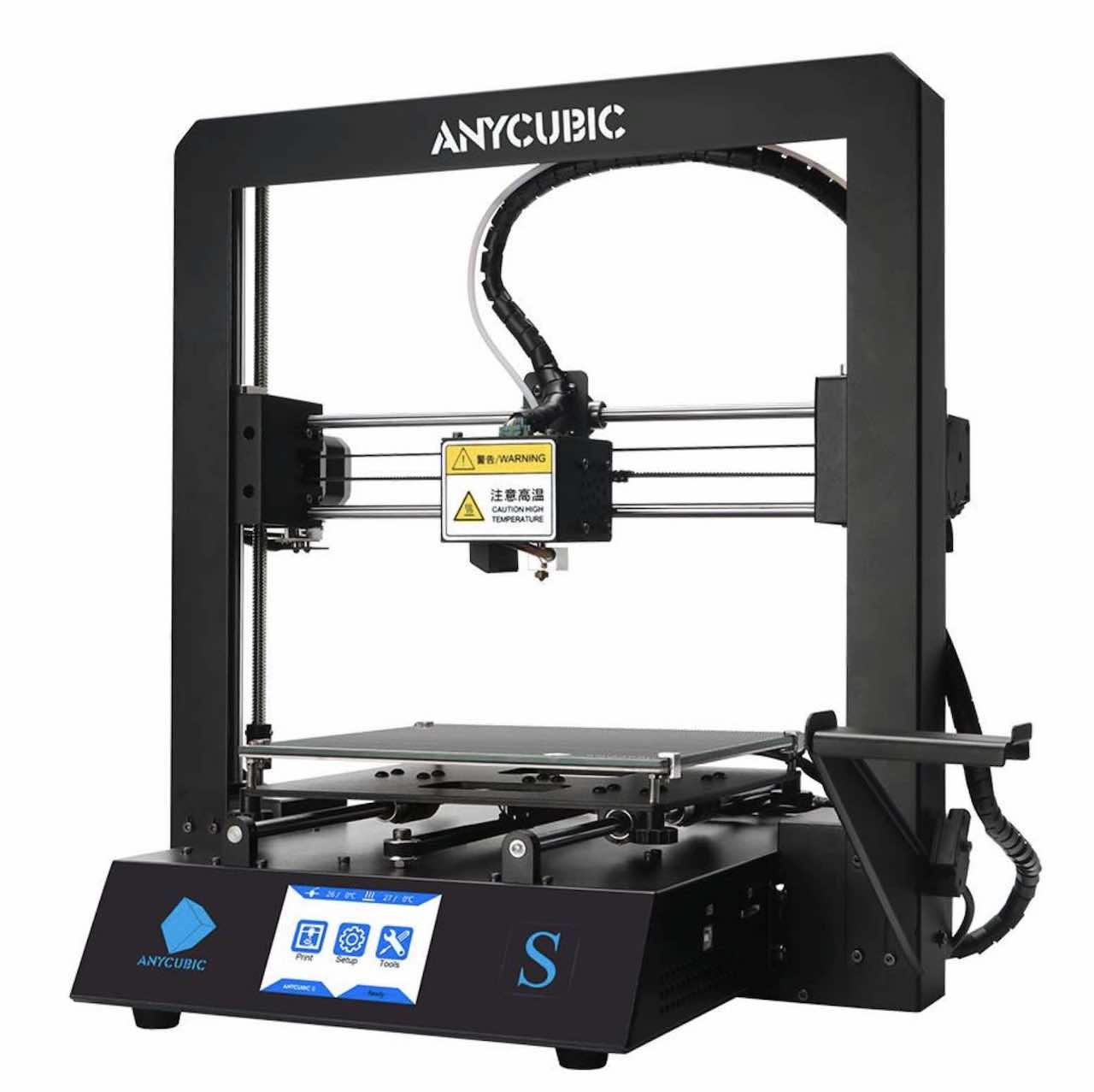
- Mega S (second generation with Anycubic 0.0.2 display)

- Mega X (first generation with DWIN / DGUS II display)

- Mega X (second generation with Anycubic 0.0.2 display)

- Mega Pro (Mega S with laser, BMG extruder and TMC drivers on X and Y. The Anycubic 0.0.2 display is always used)

- Chiron (first generation with Anycubic 1.0 display)

- Chiron (second generation with Anycubic 0.0.2 display)

- 4MAX Pro (first generation made out of plastic with 270x210x190mm build volume)

- 4MAX Pro v2 (second generation of the 4MAX Pro with BMG direct extruder)

With every printer it is possible to operate it in its original state, or replace all stepper motor drivers with TMC22xx. In addition, Autoleveling sensors such as the BLTouch retrofit. Since version 1.3.0 it is also possible to additionally integrate a Wifi module and thus to control the printer completely via a web interface.
If one of these upgrades applies to your own printer, a special firmware version must be installed for each.
As can be seen above, there are different printers with different displays. To find out which one you have, it is enough to switch on the printer and look at the colors, fonts and any animations that may be present. Detailed information on the individual displays is available here.
You can recognize it immediately after switching on. The background is white, the writing is blue. This display was built into the i3 Mega, Mega S and Chiron for a long time and works very reliably. There are no known problems with the operation.

If you click on "Tools" in the main menu, you come to a single page that contains all additional functions. Some functions are still hidden behind individual buttons, but apart from large rectangular blue buttons, there is no possibility of interaction.

If you install this firmware, the special menu is also displayed without any problems.

After switching on you get an elaborate boot animation (on the Mega X with MP3 sound) and you notice the quite high resolution and the somewhat soft display. The "Ready" lettering is clean and filtered.

If you click on "Tools" in the main menu, the differences to the Anycubic 1.0 display become clear. The menu is divided into several pages and the arrow with which you can change pages is animated.
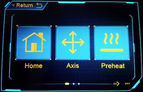
The special menu is razor sharp, reacts quickly, but sometimes behaves with a delay because this display communicates more slowly with the mainboard than the Anycubic 1.0.

If you switch on a printer with this display, you get a boot animation similar to that of the Mega X, but with fewer frames per second. The "Ready" lettering is very sharp, but angular and not smooth like on the DGUS II.

If you click on "Tools" in the main menu, you can see how much the menu is based on the structure of the DGUS II (since the graphics were probably also built with the DWIN toolset). However, there is no animation whatsoever. In addition, there is no MP3 sound, just a soft beep.
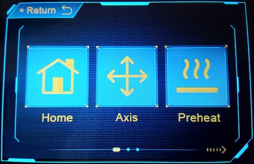
The special menu on this display has a peculiarity: Since this display does not allow any text to be written into the file list, virtual files had to be created, which even have the .gcode extension and when the update button was pressed can be loaded to execute menu functions. Since the handling differs fundamentally from the two previous displays in terms of programming, a special firmware version must be used for this, which can be recognized by the text "_DGUS" in the file name.

- Anycubic 1.0 display -> normal firmware
- Original DGUS II display -> normal firmware
- Anycubic 0.0.2 DGUS Clone Display -> _DGUS Firmware
This section is basically only relevant if you have installed a BLTouch or comparable autoleveling sensor and operate it via the servo connection on the main board. If you do not have installed a BLTouch or similar, you can skip this entire section and continue with point 4. However, I still recommend opening your own printer once in order to at least tighten the screws for the main supply lines on the motherboard.
The first version of the Trigorilla mainboard was installed until mid-2019. It can be recognized by the Trigorilla logo without a version number and by the small blue terminals for the power supply.
Pin assignment of the servo port:
SERVO0_PIN 7SERVO1_PIN 6SERVO2_PIN 5SERVO3_PIN 4
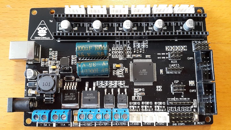
The second version of the Trigorilla mainboard was installed until the end of 2019. It can be recognized by the Trigorilla logo with the version number 1.1 and the small blue terminals for the power supply. This is (as far as I know) the only mainboard version with a different pin assignment of the servo connection!
Pin assignment of the servo port:
SERVO0_PIN 5SERVO1_PIN 4SERVO2_PIN 11SERVO3_PIN 6

The third version of the Trigorilla mainboard was installed until mid-2020. It can be recognized by the missing logo and the version number 0.0.2 and by the large green terminals for the power supply. Here the pin assignment for the servo connection was set back to the original one, so that this board behaves like a Trigorilla 1.0.
Pin assignment of the servo port:
SERVO0_PIN 7SERVO1_PIN 6SERVO2_PIN 5SERVO3_PIN 4
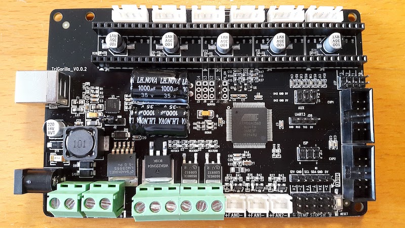
The third version of the Trigorilla mainboard is still used today. It can be recognized by the new Trigorilla + logo and version number 0.0.3 and by the large green terminals for the power supply. In addition, the display hub circuit board is integrated into the board so that the display and the SD card reader can be connected directly with a ribbon cable. The pin assignment for the servo connection has not changed again, so that this board also behaves like a Trigorilla 1.0.
Pin assignment of the servo port:
SERVO0_PIN 7SERVO1_PIN 6SERVO2_PIN 5SERVO3_PIN 4

Now that we know the different printers and the displays installed by Anycubic, it is no longer difficult to find the right firmware. An example of the appropriate firmware can be found below.
_1G stands for the first generation of the i3 Mega with only one Z end stop. This firmware is not suitable for the normal i3 Mega!
_S stands for the Mega S with the titanium extruder.
_P stands for the Mega P with the BMG extruder.
_X stands for the Mega X.
_TMC stands for Trinamic TMC motor driver. The direction of rotation of the motors is inverted and the control of the motors for TMC drivers is optimized.
_DGUS stands for the" new "blue / yellow DGUS clone display, which otherwise cannot display a special menu.
_BLT stands for the BL-Touch version with auto-leveling sensor. Manual mesh leveling is deactivated here.
_10 stands for the Trigorilla_14 v1.0 mainboard, which should normally be the standard. (only relevant for BLTouch)
_11 stands for the Trigorilla_14 v1.1 mainboard, on which the pin assignment for the servo port has changed. (only relevant for BLTouch)
As a first example we take a second generation Anycubic i3 Mega with 2 Z-Endstops, as they are used with every other Mega printer. The current firmware version is always made up of 3 numbers, which are separated by a point. For this example I will use version 1.2.0, as this is the current version at this point in time (July 2021).
The right firmware for a completely untouched i3 Mega would be MEGA_1.2.0.hex.
However, if it is one of the first i3 Mega printers that were delivered with only one limit switch on the Z-axis, we have to use the firmware for the first generation: MEGA_1G_1.2.0.hex.
Similarly, the file name changes or expands depending on the desired functions.
An Anycubic Mega S of the second generation, in which all motor drivers have been replaced by TMC2208 and which has a display that can be clearly identified as Anycubic 0.0.2 (blue background, no animations, yellow writing). In addition, a BLTouch sensor was installed according to the instructions and connected to a Trigorilla 0.0.2: MEGA_S_DGUS_TMC_BLT_10_1.2.0.hex
Now we know what firmware we need and download it:
Now that we have found out which firmware is suitable for our printer, it can be installed very easily using the Cura firmware update function. To do this, we close all programs that may still have access to the printer, connect the printer to the PC via USB and open Ultimaker Cura.
In the first step we open the drop-down menu with the printers and click on "Manage Printers"

In the window that has opened, we select our printer and click on "Update Firmware"
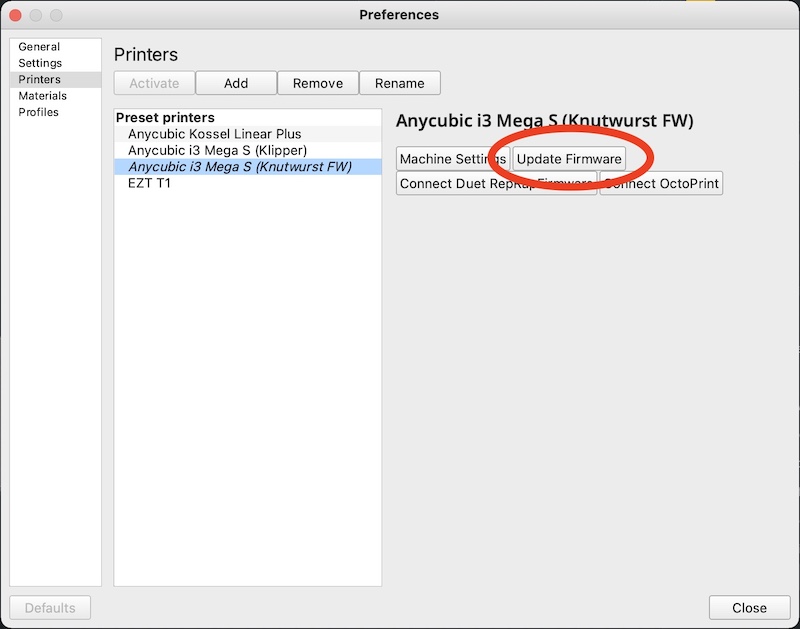
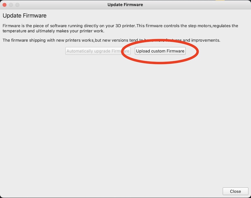
If the printer is correctly connected to the PC, the "Upload Custom Firmware" button can be pressed and the .hex file that has just been downloaded can be selected.
The update is then carried out automatically and the printer restarts after completion.
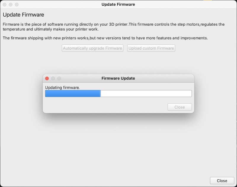
The firmware is now installed and can be used.
After the firmware has been installed for the first time, the default settings must be loaded. This is necessary because this custom firmware uses a writable memory (EEPROM) on the mainboard in which we can save individual settings. These settings are always read out when the device is switched on and are always expected at the same place. If another firmware is now writing data to this area, this can lead to a malfunction of the printer if the memory is not initialized at least once at the beginning.
We do this by going into the new Special Menu. This is located in the "Print" menu, which usually lists the gcode files that are on the SD card.
To confirm individual menu items, do not press the "Print" button as usual, but rather the circle to update.

In the special menu we first select "Load FW Defaults" (firmware default settings) and confirm with the circle. The execution is acknowledged with a beep.

Then we can save the settings that have just been loaded and thus complete the setup. For this we select "Save EEPROM" and confirm again with the circle.
The default setting is now complete and theoretically it is now possible to print.
This custom firmware offers some innovations in the printing behavior and also pushes the physical limits of the printer to the full without damaging it.
These settings are very important for this:
The Mega S and the Mega P have a larger print bed (240x220 mm) on which the glass plate is attached with side brackets. The print head or the nozzle cannot cover the entire bed and reach every corner, but it is possible to print larger than 210x210mm, as the hardware allows it. That is why the firmware allows a larger print space to be used with these two printers than is specified by the manufacturer.
The following values must therefore be entered in order to use this and to place the component back in the middle of the bed:
X (Width) = 225 mm
Y (Depth) = 220 mm
Z (Height) = 210 mm

In order to achieve the best print result, which is possible with a 16 MHz Atmel microcontroller as it is built into the Trigorilla mainboard, the resolution and deviation in the slicer must be limited. The values that the standard profile from Cura provides for the i3 Mega are not adapted to the computing power and can lead to stuttering and unsightly blobs in long curves. Prusa itself therefore specifies an even lower resolution for the Prusa i3, but the following values have proven to be ideal.
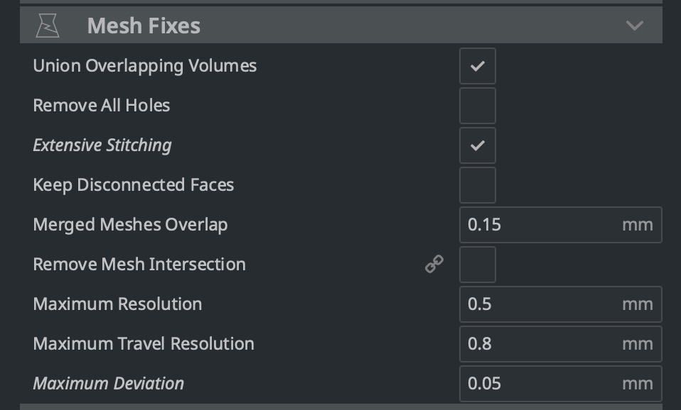
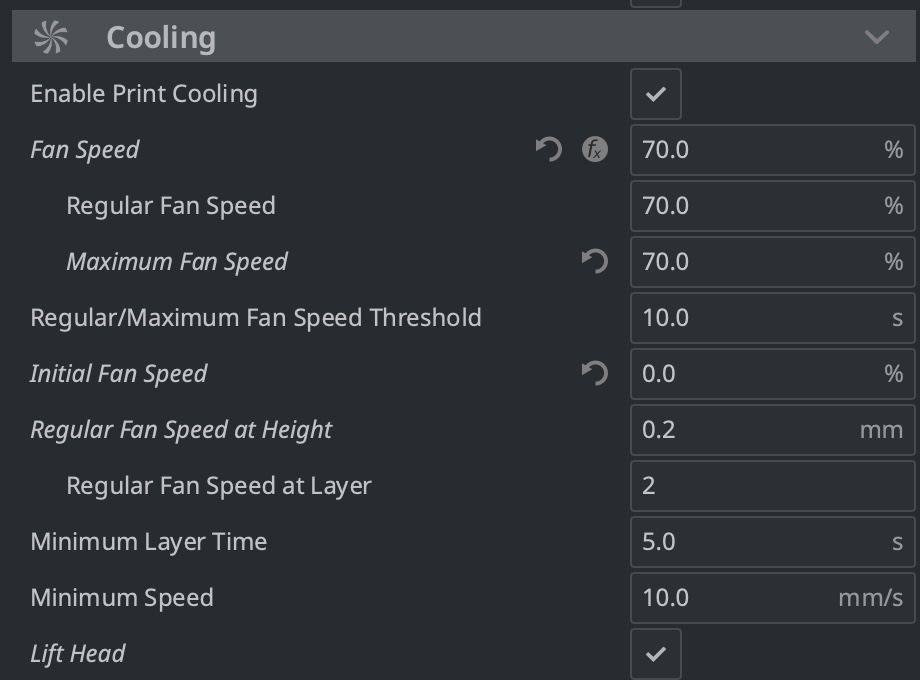
The component fan, which blows directly under the nozzle to cool the filament, is controlled in speed via pulse width modulation (PWM). There is a simple procedure behind the complicated term: The power supply (12V) is switched on at regular intervals (PWM frequency) for a certain period of time (PWM duty cycle). After this period of time, the power is switched off again. The longer the ON phase, the faster the fan rotates.
In the original firmware, Anycubic limited this maximum PWM duty cycle to the value 0.7 or multiplied any set value by 0.7. Thus, a fan set to 100% only rotated at 70% of its possible power.
There is no such lock in this firmware, so it is easily possible to install other (quieter) fans that can be operated continuously with a full 12 volts.
However, this has the consequence that the original fan from Anycubic now rotates 30% faster than it should and thus the component may cool down much too much. Since the air flow is also not ideal, it can happen that the nozzle is cooled down too much, and thus temperature errors occur in the print.
For this reason, the fan in the slicer must not be set above 70%!
This step is optional. If you want, you can have a look at my personal start and end code for Cura here. The explanation is in the comments. If a Gcode is unclear, I recommend reading the official Marlin documentation (also linked there).
This step is also optional and should only be carried out if the extruder has been modified or changed. Normally, all common extruders are already entered in the firmware. However, if you notice that too much or too little filament is being conveyed, you can still calibrate the extruder.
There are many instructions for this on the Internet, but basically every statement can be reduced to a minimum:
G92 E0 (set extruder to 0)
G1 E100 (convey 100mm filament)
If, instead of the specified 100mm, too much or too little is being conveyed, the following commands can be used to change the micro-steps that are required for one millimeter.
M92 Exx.x (set new value) M500 (save)
This point is also optional!
The PID controller (proportional-integral-derivative controller) reliably controls the heating of bed and nozzle. "Tuning" overwrites the values I have set and the heating is recalibrated. This is important when printing significantly higher temperatures and this may result in fluctuations.
The standard PID tuning can be carried out directly from the special menu and takes several minutes. A beep confirms successful tuning.
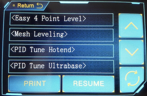
However, it is important to know that under certain circumstances (very high or very low ambient temperature) the PID tuning even worsens the heating behavior. Here it is then necessary to reload the default / standard values.
This page, as well as various installation instructions, frequently asked questions etc. can also be found in the Wiki
*Es muss jetzt keine großzügige Spende sein. Ein paar Cent reichen um mir zu zeigen, wer überhaupt Interesse daran hat und wem die Weiterentwicklung wichtig ist. So bleibt die Motivation da und ich weiß einfach, dass ich nicht für die Tonne programmiere ;)
*It doesn't have to be a generous donation. A few cents are enough to show me who is interested in further development. So the motivation stays and I just know that I am not programming for the bin ;)
