-
Notifications
You must be signed in to change notification settings - Fork 245
GHIDRA
Recently, the NSA released binaries and source code for the GHIDRA reverse engineering framework. While many professionals use this as an opportunity to air their many grievances against IDA Pro's purchasing department, and many students use this as an opportunity to complain about IDA Pro's pricing, we should kindly focus instead on what nifty things might be done with this tool.
These notes will show you how to load the firmware into GHIDRA, then import symbols from the md380tools reverse engineering project.
GHIDRA seems to have been designed with firmware in mind, and it happily supports loading raw binaries, so long as you know a trick or two.
Let's begin by File/New Project to create a new Non-Shared project. (If you begin this as a Shared project, you will need to have an exclusive checkout while changing the memory layout in later steps.)
Once your project as been opened, load
md380tools/firmware/unwrapped/D013.020.img or any other unwrapped
firmware image. (These are produced by the Makefile scripts from
poorly encrypted firmware updates on the Internet.)
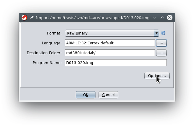
We must set the Language to little-endian ARM Cortex
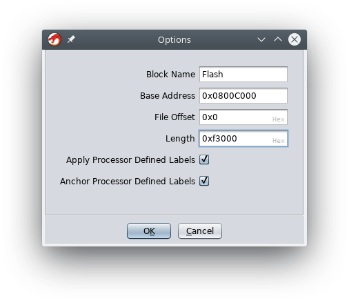
(ARM:LE:32:Cortex), and use the Options pane to set the proper
loading address. These images contain Flash memory beginning after
the 768k bootloader, so we will need a loading address of 0x0800C000.


After the image has been loaded, we now have Flash loaded to the proper address, but have we have no RAM, and neither IO nor function symbols. Let's begin by finding the function entry points with the auto-analyzer, then importing their proper names.
When you first double-click the D013.020.img image after loading it,
GHIDRA will prompt you to run the auto-analyzer with any number of
default options. By choosing the default options and waiting a
minute, you will find hundreds of functions accurately identified for
you.
Unfortunately, not everything can be instantly identified. For
example, the table located at the beginning (0x0800C000) is the
Interrupt Vector Table, but it is not located at the default address.
GHIDRA is smart enough to recognize many of these entries, and the
exceptions are things like the initial stack address (at 0x0800C000)
and the RESET vector (at 0x0800C004) that are never called by the
applications own code. It's worth chasing down a few of these to see
how the auto-analyzer fails, but we won't concern ourselves with them
in this tutorial.
You should also take a moment to consider what you haven't had to do. Unlike IDA Pro and Binary Ninja, GHIDRA's concept of a Language setting allows it to know before hand that this binary is entirely Thumb2, with no classical ARM instructions and no need to set a virtual register. You never needed to
Before we continue with importing other artifacts from the MD380Tools project, let's take a look at some handy functions and use them to find others.
Let's start with the lowest levels of the SPI Flash driver. The SPI Flash is an external Flash chip that contains the radio's codeplug, defining frequencies and configuration settings. In reverse engineering new functions, it is incredibly helpful to watch them read their settings out of the SPI Flash chip.
Begin by navigating to the md380_spi_sendrecv function at
0x080314bd. Do this by hitting G in the disassembly view, then
giving GHIDRA the address, which it will round down to 0x080314bc.
(Internally, ARM has odd addresses for all Thumb functions, but GHIDRA
does not follow this convention.) Once there, select the function's
name and hit the F key to edit the function definition, changing the
name to md380_spi_sendrecv. Think of this function as getchar()
and putchar(char) wrapped into one; it sends a single byte out of
the SPI bug while returning the byte that crossed back at the same
time.
Next, navigate to 0x080314bd and look at its decompiled view. You
can see that this sends the byte 0x03, followed by the three bytes of
the second parameter beginning with the most significant, and then all
the bytes pointed to by the first parameter for a count of the third
parameter.
void FUN_080314bc(undefined *puParm1,uint uParm2,short sParm3)

{
  undefined uVar1;

  FUN_0803152a();
  md380_spi_sendrecv(3);
  md380_spi_sendrecv(uParm2 >> 0x10 & 0xff);
  md380_spi_sendrecv(uParm2 >> 8 & 0xff);
  md380_spi_sendrecv(uParm2 & 0xff);
  while( true ) {
    if (sParm3 == 0) break;
    uVar1 = md380_spi_sendrecv(0xa5);
    *puParm1 = uVar1;
    puParm1 = puParm1 + 1;
    sParm3 = sParm3 + -1;
  }
  FUN_08031546();
  return;
}
From the SPI Flash's datasheet, we know that 0x03 is the command to
read data bytes form the chip. The real name of this function is
md380_spiflash_read, and chasing down the addresses that it reads
allows us to match functions in the firmware with their meaning in the
codeplug. Since we know that the chip must be selected before the
read, and deselected after, we can guess that FUN_0803152a is really
md380_spiflash_enable and FUN_08031546 is really
md380_spiflash_disable without even having to read their code.
Using the L key in the decompiled view to define parameter,
function, and variable names, we can come up with a much cleaning
decompilation. The ; key allows you to mark comments.
void md380_spiflash_read(undefined *buffer,uint adr,short length)

{
  undefined currbyte;

  md380_spiflash_enable();
                    /* 0x03 = READ DATA BYTES command */
  md380_spi_sendrecv(3);
  md380_spi_sendrecv(adr >> 0x10 & 0xff);
  md380_spi_sendrecv(adr >> 8 & 0xff);
  md380_spi_sendrecv(adr & 0xff);
  while( true ) {
    if (length == 0) break;
    currbyte = md380_spi_sendrecv(0xa5);
    *buffer = currbyte;
    buffer = buffer + 1;
    length = length + -1;
  }
  md380_spiflash_disable();
  return;
}
And having these fine functions, we can chase down related ones.
Right-click on the function name in the disassembly view, and chose
Show References to to show every caller of the function. (Or
Ctrl+Shift+F.) Doing this for md380_spiflash_enable() gives us a
half dozen functions that interact with the SPI Flash, such as
md380_spiflash_write(), md380_spiflash_sektor_erase4k(), and
md380_spiflash_block_erase64k(). Doing this for
md380_spiflash_read() gives us every function that reads from SPI
Flash, and from those addresses we can know what they are reading.
For example, consider this unknown function which reads twenty bytes from 0x2040.
undefined4 FUN_080226c0(void)

{
  undefined4 unaff_r7;

  md380_spiflash_read(DAT_08023398,0x2040,0x14);
  return unaff_r7;
}
In the incomplete CHIRP driver at md380tools/chirp/md380.py, we see
that 0x2000 is a configuration structure containing two twenty-byte
strings for the startup text. Sure enough, our mystery function is
Get_Welcome_Line1_from_spi_flash and we can hook or patch it to
change what text is displayed at startup!
#seekto 0x2000;
struct {
    u8 unknownff;
    bbcd prog_yr[2];
    bbcd prog_mon;
    bbcd prog_day;
    bbcd prog_hour;
    bbcd prog_min;
    bbcd prog_sec;
    u8 unknownver[4];       //Probably version numbers.
    u8 unknownff2[52];      //Maybe unused?  All FF.
    char line1[20];         //Top line of text at startup.
    char line2[20];         //Bottom line of text at startup.
...
Now, it's cool that we can trace these settings from SPI Flash images,
but it would be nicer if we could just look at 0x08023398 in RAM to
see what bytes had been loaded there. To do that, we'll need to
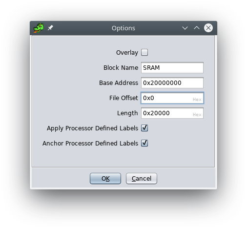
create a region for 128k at 0x20000000. (The STM32F405 also has 64k
at 0x10000000 but this is rarely used by the linker for static
buffers.)
Choose Add To Program from the File menu to add a second image.
Chose md380tools/cores/d13020-core.img, which is a live RAM dump
made over USB from a booted copy of D13.020. In the options pane, you
must set the loading address to 0x20000000.

Now we can navigate to 0x2001E3FC where the string is stored.
Define the first type to be wchar16 then press [ to create an
array of 10 elements. Doing the same at 0x2001e410 for the second
line, you can see the two startup lines of my radio configuration in
SRAM!
        2001e3fa 00              ??         00h
        2001e3fb 00              ??         00h
        2001e3fc 4b 00 4b        wchar16[   u"KK4VCZ    "
                 00 34 00
                 56 00 43
        2001e410 33 00 31        wchar16[   u"3147092   "
                 00 34 00
                 37 00 30
As one last little hassle, the decompiler is confused about ARM literal pools. See, ARM doesn't really have 32-bit immediates; instead, it fakes them by having pools of data between functions, which are referenced relative to the program counter.
GHIDRA becomes confused because, in theory, these literal pools might
be overwritten with new 32-bit values. Because of this confusion, the
decompiler tells you that the variable DAT_080233b0 is passed along,
when in fact the literal 0x2001E410 is the only value that will ever
be at 0x080233b0.
void Get_Welcome_Line2_from_spi_flash(void){
  md380_spiflash_read(DAT_080233b0,0x2054,0x14);
  return;
}
DAT_080233b0 XREF[1]: Get_Welcome_Line2_from_spi_flash
080233b0 10 e4 01 20 undefined4 2001E410h
In practice, this Flash memory is rather complicated to change, and code is not directly writable. So we need to tell the decompiler that the Flash page is not writable in Window/Memory Map. Simply unchecking the box and saving the new memory map will correct the decompilation, showing us that the string being passed is "3147092". We can of course give it a clearer name and check for cross-references, in order to know which other functions use the second welcome line.

void Get_Welcome_Line2_from_spi_flash(void){
  md380_spiflash_read((char *)u_3147092_2001e410,0x2054,0x14);
  return;
}FINISHME
FINISHME