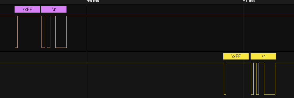
This is my attempt at reverse engineering and documenting the serial protocol used between the radio and the control panel. Documentation is split into chunks please see the sections below.
- Panel: Readme
- Panel: Buttons: byte & ASCII values
- Panel: Display segments
- Panel: S Meter Display Values
- Radio: Power up sequence
- UART (idle high), 5V TTL: RXO <- TXO. TXO -> RXO
- 57600bps 8N1 (8 bits, no parity, 1 stop bit) for both lines
- A lot of values are ASCII.
Pin  Name    Description
1    GND     Speaker ground
2    8V      Control panel power (measured 9v..)
3    GND
4    RX      5v TTL UART (radio to control head / panel)
5    TX      5v TTL UART (from control head / panel to radio)
6    AF      Speaker Audio
COMMAND -> DATA VALUE -> ACK
- The radio and panel have their own ACK intervals, both have timeout logic.
- Interval on the radio is ACK every 5 seconds.
- Panel interval is every 2 seconds but received "interrupt ACK" from radio on third second, responds immediately after.
--
Adjusting AF output (Volume) is contained purely to the panel. ARCP-480 can adjust volume as well but this is probably done by changing the voltage the speaker sees?
Valid volume values are from V00 to VFF


