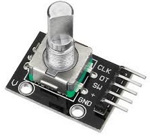
This is an optimized three speed Rotary Encoder library for Arduino which supports:
- Full step Rotary Encoder types.
- Detect three rotation speeds.
- Configurable rotation speed sensitivity.
- Polling and interrupt based.
- Single or multiple Rotary Encoders.
- Optional Rotary button.
- Pin state table in flash.
The difference between a full step or half step Rotary Encoder type is how the data signals of the two pins are generated. It depends on the mechanical construction of the notches and contacts inside the Rotary Encoder.
Please refer to the ErriezRotaryEncoderHalfStep library for half step Rotary Encoders. Experiment with the half step and full step libraries which works optimal for your Rotary Encoder.
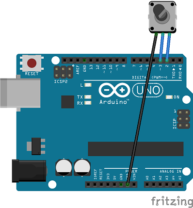
Connect the two rotary pins to the DIGITAL pins of an Arduino board.
A third rotary button pin is not used in the Rotary library, but can be used in the sketch.
Tested with Arduino IDE v1.8.13 on hardware:
- Arduino UNO
- Arduino Nano
- Arduino Micro
- Arduino Pro or Pro Mini
- Arduino Mega or Mega2560
- Arduino Leonardo
- WeMos D1 R2 & mini (ESP8266)
Other supported targets:
- ESP8266
- ESP32
- SAMD21
- STM32F1
Both rotary pins must be connected to a DIGITAL pin with interrupt support, such as INT0 or INT1. This is chip specific. Please refer to the documentation of your board or attachInterrupt().
The connection below can be used for polled and interrupts. An optional button pin can be connected to DIGITAL pin 4.
| Rotary pin | Arduino UNO/NANO/Mega2560/Leonardo board |
|---|---|
| 1 | DIGITAL pin 2 (INT0) |
| 2 | DIGITAL pin 3 (INT1) |
| Button (optional) | DIGITAL pin 4 |
| GND | GND |
Note that some ESP8266 pins mixes ESP8622 GPIO pins with Arduino digital pins. Connect a Rotary Encoder to the following pins which can be used with polled and interrupt examples:
| Rotary pin | ESP8622 pin | Text on board / WeMos D1 & R2 |
|---|---|---|
| 1 | GPIO13 | D7 (MOSI) |
| 2 | GPIO12 | D6 (MISO) |
| Button (optional) | GPIO14 | D5 (SCK) |
| LED (Not used) | GPIO2 | D4 |
| GND | GND | GND |
Note: An external pull-up resistor is required when a pin does not have an internal pull-up.
// Connect the rotary pins to the WeMos D1 R2 board:
#define ROTARY_PIN1         12
#define ROTARY_PIN2         13
#define ROTARY_BUTTON_PIN 14The following examples are available:
- Rotary | Interrupt | InterruptFullStepBasic
- Rotary | Interrupt | InterruptFullStepButton
- Rotary | Interrupt | InterruptFullStepCounter
- Rotary | Polled | PolledFullStepBasic
- Rotary | Polled | PolledFullStepButton
- Rotary | Polled | PolledFullStepCounter
- Rotary | Polled | PolledFullStepMultiple
Read rotary with polling
#include <ErriezRotaryFullStep.h>

// Connect rotary pins to the DIGITAL pins of the Arduino board
#define ROTARY_PIN1   2
#define ROTARY_PIN2   3

// Enable ONE of the three constructors below with different number of arguments:

// Initialize full step rotary encoder, default pull-up enabled, default
// sensitive=100
RotaryFullStep rotary(ROTARY_PIN1, ROTARY_PIN2);

// Or initialize full step rotary encoder, pull-up disabled, default sensitive=100
// RotaryFullStep rotary(ROTARY_PIN1, ROTARY_PIN2, false);

// Or initialize full step rotary encoder, pull-up enabled, sensitive 1..255
// A higher value is more sensitive
// RotaryFullStep rotary(ROTARY_PIN1, ROTARY_PIN2, true, 150);

void loop()
{
  int rotaryState = rotary.read();

  // rotaryState = -3: Counter clockwise turn, multiple notches fast
  // rotaryState = -2: Counter clockwise turn, multiple notches
  // rotaryState = -1: Counter clockwise turn, single notch
  // rotaryState = 0:  No change
  // rotaryState = 1:  Clockwise turn, single notch
  // rotaryState = 2:  Clockwise turn, multiple notches
  // rotaryState = 3:  Clockwise turn, multiple notches fast
}
Read rotary with interrupts
#include <ErriezRotaryFullStep.h>

// Connect rotary pins to Arduino DIGITAL pins with interrupt support:
//
// +-----------------------------------+--------------------------+
// |              Board                |  DIGITAL interrupt pins  |
// +-----------------------------------+--------------------------+
// | Uno, Nano, Mini, other 328-based  |  2, 3                    |
// | Mega, Mega2560, MegaADK           |  2, 3, 18, 19, 20, 21    |
// | Micro, Leonardo, other 32u4-based |  0, 1, 2, 3, 7           |
// +-----------------------------------+--------------------------+
//
#define ROTARY_PIN1   2
#define ROTARY_PIN2   3

// Enable ONE of the three constructors below with different number of arguments:

// Initialize full step rotary encoder, default pull-up enabled, default
// sensitive=100
RotaryFullStep rotary(ROTARY_PIN1, ROTARY_PIN2);

// Or initialize full step rotary encoder, pull-up disabled, default sensitive=100
// RotaryFullStep rotary(ROTARY_PIN1, ROTARY_PIN2, false);

// Or initialize full step rotary encoder, pull-up enabled, sensitive 1..255
// A higher value is more sensitive
// RotaryFullStep rotary(ROTARY_PIN1, ROTARY_PIN2, true, 150);

void setup()
{
  // Initialize pin change interrupt on both rotary encoder pins
  attachInterrupt(digitalPinToInterrupt(ROTARY_PIN1), rotaryInterrupt, CHANGE);
  attachInterrupt(digitalPinToInterrupt(ROTARY_PIN2), rotaryInterrupt, CHANGE);
}

void rotaryInterrupt()
{
  int rotaryState = rotary.read();

  // rotaryState = -3: Counter clockwise turn, multiple notches fast
  // rotaryState = -2: Counter clockwise turn, multiple notches
  // rotaryState = -1: Counter clockwise turn, single notch
  // rotaryState = 0:  No change
  // rotaryState = 1:  Clockwise turn, single notch
  // rotaryState = 2:  Clockwise turn, multiple notches
  // rotaryState = 3:  Clockwise turn, multiple notches fast
}- None.
Please refer to the Wiki page.

