I recently replaced my garage door, the new one (Craftsman Brand) advertised with a "Smartphone Link". This could get interesting; I was very curious how they implemented a cloud service. My first assumption was another Tuya platform service rebranded; I was wrong.
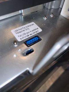
At first look, I saw this and obviously had some questions: A USB-A port (USB3.x port? What is happening in this thing??)

Further inspection - they obviously got a deal on these ports, only the 4 typical USB pins are used. However its not USB.
Probing the other side of this on the board revealed the following:
P1 - +3.3 VDC
P2 - TTL UART Tx
P3 - TTL UART Rx
P4 - ESP32 Select (more on this later)
Ground is not contained in the actual plug/header itself. The stock device uses the shield as ground. You could use the header mounts on the board for a ground on this end.
The bottom 5 pins (USB3 plug) do nothing, obviously.
This is the "cloud device" that plugs in. I'll come back to it later.

 A look at the FCC ID gives a hint (ESP32C3MINI)
Prior to opening anything up, I probed around on the header on the door opener board. I had the app connected/loaded, and wanted to figure out how their device was communicating with the door opener itself. Having probed the port already for voltages, I began probing serial communications. Most UARTS are running at 115200 these days, this was no different. Probing into a serial terminal while activating the door and lights, it was fairly easy to identify byte patterns, both commands and acknowledgements.
For the garage door opener and light control messages:
Overhead light on: [0xAA,0xAA,0x01,0x02,0x02,0x01,0x03,0x03,0x55,0x55]
Overhead light off: [0xAA,0xAA,0x01,0x02,0x02,0x01,0x04,0x04,0x55,0x55]
Door activation: [0xAA,0xAA,0x01,0x02,0x02,0x01,0x00,0x00,0x55,0x55])
And here are the "ack" messages after commands are received and/or after there is a change in any of the following. (Does not require activation via UART to provide feedback) These are sent back to the cloud dongle (Tx):
light on: [0xAA,0xAA,0x01,0x02,0x03,0x02,0x41,0x00,0x43,0x55,0x55]
light off: [0xAA,0xAA,0x01,0x02,0x03,0x02,0x40,0x00,0x42,0x55,0x55]
door is open: [0xAA,0xAA,0x01,0x02,0x03,0x02,0x01,0x00,0x03,0x55,0x55]
closing warning: [0xAA,0xAA,0x01,0x02,0x03,0x02,0x15,0x00,0x17,0x55,0x55]
door is closed: [0xAA,0xAA,0x01,0x02,0x03,0x02,0x31,0x00,0x33,0x55,0x55]
You can see the preamble, EOT, and messaging format pretty easily. I chose to get the data between the devices figured out before diving into anything else. If you send those byte arrays via serial, the door controller responds as expected.
I ran wireshark with a man-in-the-middle hotspot to see how and to whom it was communicating. It reaches out to AWS for most of it. A few interesting points: API access appears to need an access token which is generated at the remote end (AWS). Once the access token is recieved, all LAN based communication is in clear text, however the payloads are encoded. Non-Lan / WAN connections are all TLS once the key exchange happens.
===================================================================
Filter: tcp.stream eq 0
Node 0: 172.16.201.107:56265
Node 1: 172.16.201.124:80
314
POST /local_reg.json?dsn=AC000W030965871 HTTP/1.1
Host: 172.16.201.124
Content-Type: application/json
Connection: keep-alive
Accept: */*
User-Agent: Noma Field App Store/3.0.13(201) SDK: 7.0.5 (iPhone; iOS 18.0.1; Scale/2.00)
Accept-Language: en-CA;q=1
Content-Length: 81
Accept-Encoding: gzip, deflate
81
{"local_reg":{"uri":"\/local_lan","notify":0,"ip":"172.16.201.107","port":10275}}
25
HTTP/1.1 202 Accepted
Followed by the key exchange:
Filter: tcp.stream eq 1
Node 0: 172.16.201.124:60442
Node 1: 172.16.201.107:10275
162
POST /local_lan/key_exchange.json HTTP/1.1
User-Agent: ESP32 HTTP Client/1.0
Host: 172.16.201.107:10275
Content-Type: application/json
Content-Length: 105
{"key_exchange":{"ver":1,"random_1":"DG6dbMEnRolqrAjH","time_1":355921561731160,"proto":1,"key_id":5484}}
HTTP/1.1 200 OK
Accept-Ranges: bytes
Content-Length: 57
Content-Type: application/json
Date: Sat, 09 Nov 2024 13:54:14 GMT
{"random_2":"N8fOtOT91k4630SH","time_2":1731160454851055}
GET /local_lan/commands.json HTTP/1.1
User-Agent: ESP32 HTTP Client/1.0
Host: 172.16.201.107:10275
Content-Type: application/json
Content-Length: 0
HTTP/1.1 200 OK
Accept-Ranges: bytes
Content-Length: 108
Content-Type: application/json
Date: Sat, 09 Nov 2024 13:54:16 GMT
{"enc":"XFTrOPTskZ13DHu3ayrQhp5d1q+WiJI0ICaRB8hj64Q=","sign":"WlJwEN2ifSNi8njmorecD3TL0TlK7l/ixhz0fmTRFDw="}

============================================================
Not so lucky there. The ESP32 is doing the lifting here as we see. I messed around for a few hours and didn't get very far, so moved on to the next part.
So basically, I don't care about their API for control and status. I'll write my own for local control (I use homebridge and homeassistant). I'm more interested in using their ESP32 to do the work for me: Let's look at it:
As advertised, it's and ESP32C3 Mini - Wifi and BTLE capable.
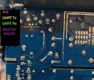
I tried dumping the flash to run get an ELF binary to hopefully decompile in ghidra. Even to do this we had to get a better handle on the hardware first. Conveniently the backside gives us more clues via test points:

A few things jump out:
- The serial port out of the device to the door opener is not the main uart (Serial0)
- The Boot and Enable pads are going to be our ticket to the flash on this SoC. :)
- Everything we need is exposed. Woo.
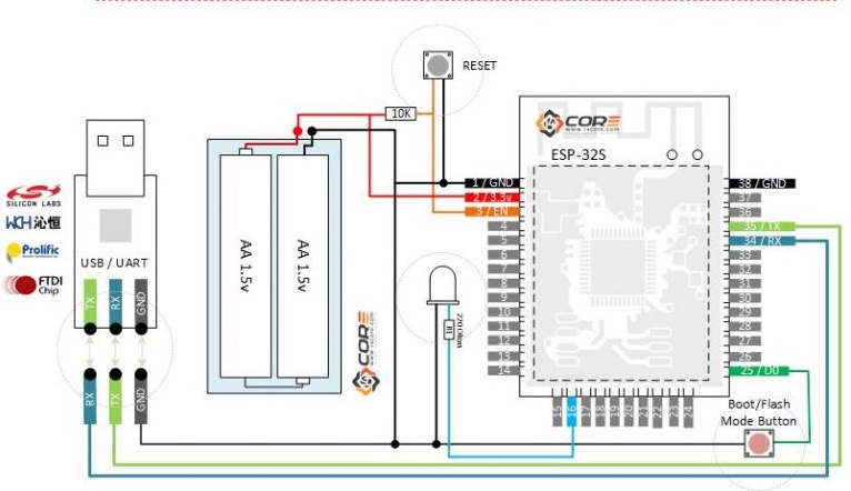
See here for a visual representation to flash this thing:

A little workup on a breadboard and we will have access.
Boot/Flash needs to be grounded with a quick (-) pulse on reset and it will halt the processor and wait for instructions via UART0 (the pads on the circuit board). Wire up a USB/TTL serial converter, use an arduino with the chip removed, whetever you need. You'll be manually resetting this thing as it's not a dev board with the convenience of DTS on the USB to do the work for you.

I opted to wire in the TTL serial lines (on the USB header) as well, as those were the ones communicating the the actual door opener. It's evident here they are using 2 seperate UARTS on the ESP32. I'll need access to those anyways to help figure out whats what on the GPIO pins. UART0 is on the test pads, and are connected via serial to my machine via USB/TTL adapter.
After resetting it manually, bingo with esptool:
(0x400000 is due to the 4M flash, but it's not that simple if your flash size is different. See here for an easier way to understand it.)
Lets dump the flash:
/Arduino15/packages/esp32/tools/esptool_py/4.6/esptool --chip esp32c3 --port /dev/cu.usbmodem14201 --baud 115200 read_flash 0 0x400000 dump.bin

esptool.py v4.6
Serial port /dev/cu.usbmodem14201
Connecting....
Chip is ESP32-C3 (revision v0.4)
Features: WiFi, BLE
Crystal is 40MHz
MAC: ec:da:3b:1d:aa:f4
Uploading stub...
Running stub...
Stub running...
4194304 (100 %)
4194304 (100 %)
Read 4194304 bytes at 0x00000000 in 373.5 seconds (89.8 kbit/s)...
Hard resetting via RTS pin...
After a lot of messing around with partitions, on the dump, it was evident they had encrypted the flash. More headaches. The ESP devices if configured (e-fuse) for encrypted flash, will enrypt it on first run following upload. This also presents itself as errors on startup if you try and upload your own code. It expects encrypted. It will take it, but it wont run. This got in the way of snooping through their binaries, but I didn't want to use their stuff anyways (just the ESP32). The next step, you CAN revert an encrypted flash back to clear, however it can not be encrypted again. Oh well. This is done by burning an e-fuse on the chip: Running espfuse for a summary we confirm as much:
espefuse.py -p  /dev/tty.usbserial summary
espefuse.py v4.8.1
Connecting....
Detecting chip type... ESP32-C3
=== Run "summary" command ===
EFUSE_NAME (Block) Description  = [Meaningful Value] [Readable/Writeable] (Hex Value)

----------------------------------------------------------------------------------------
Calibration fuses:
K_RTC_LDO (BLOCK1) BLOCK1 K_RTC_LDO = 80 R/W (0b0010100)
K_DIG_LDO (BLOCK1) BLOCK1 K_DIG_LDO = -20 R/W (0b1000101)
V_RTC_DBIAS20 (BLOCK1) BLOCK1 voltage of rtc dbias20  = 156 R/W (0x27)
V_DIG_DBIAS20 (BLOCK1) BLOCK1 voltage of digital dbias20  = 8 R/W (0x02)
DIG_DBIAS_HVT (BLOCK1) BLOCK1 digital dbias when hvt  = -16 R/W (0b10100)
...
[lots more here I cut]
...
Tada, bit 1 set for crypto.
SPI_BOOT_CRYPT_CNT (BLOCK0)  Enables flash encryption when 1 or 3 bits are set  = Enable R/W (0b001)
and disables otherwise
So, lets burn the fuse to open it back up and brick their code entirely:
espefuse.py -p /dev/tty.usbserial burn_efuse SPI_BOOT_CRYPT_CNT
espefuse.py v4.8.1
Connecting...
Detecting chip type... ESP32-C3
=== Run "burn_efuse" command ===
The efuses to burn:
from BLOCK0
- SPI_BOOT_CRYPT_CNT
Burning efuses:
- 'SPI_BOOT_CRYPT_CNT' (Enables flash encryption when 1 or 3 bits are set and disables otherwise) 0b001 -> 0b011
Check all blocks for burn...
idx, BLOCK_NAME,  Conclusion
[00] BLOCK0 is not empty
(written ): 0x000000008000000000000000040400000000000100800100
(to write): 0x000000000000000000000000000c00000000000000000000
(coding scheme = NONE)
.
This is an irreversible operation!
Type 'BURN' (all capitals) to continue.
>>BURN
BURN BLOCK0  - OK (all write block bits are set)
Reading updated efuses...
Checking efuses...
Successful
Ok so now I should be able to upload some new code, this device is all mine now. I wrote a few scripts to pulse pins as outputs and inputs to determine what was what (with LED's on the traces we have access to). After some probing and many code iterations, here is the final:
GPIO18 - USB Header Pin 2 [Also drives onboard Blue LED via TTL inverter]
GPIO19 - USB Header Pin 3 [Also drives onboard Red LED via TTL inverter]
Note: The stock firmware has these gpio's configured as UART1 for serial communication with the external equipment
GPIO3 - The [non-grounded] side of the tactile switch on the board. You could burn off the switch an extend the pad for something else easily. Or whatever else you would like.
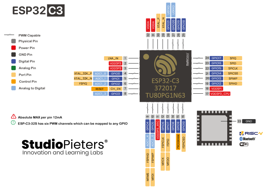
Looking at the pinout, we dont get anything glamorous on GPIO 18 or 19, and 3 has an ADC so thats OK I guess.
I wrote code to basically duplicate their functionality but locally. It connects to my IoT wifi A/P, bridges sockets<-->serial to the opener so that I can issue commands and monitor the status, but entirely without them (or their cloud service) having anything to do with it. I connect via a TCP socket from a python script to read and send commands transparently as though we were sitting right on the UART on the device. Handy to build whatever you want to integrate in to your own cloud service and cut out the middle-man. This is a pretty powerful little chip (Didn't even touch on how this could integate via BTLE!).

