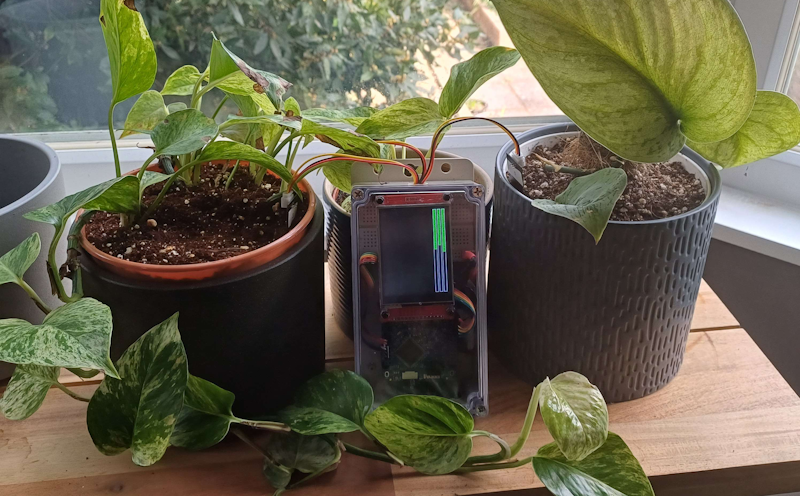
This program reads three soil moisture sensors and displays their readings as a progress bar on the ILI9341 SPI TFT display.
The SPI_TFT_ILI9341 library is originally from https://os.mbed.com/teams/components/code/SPI_TFT_ILI9341/ however I have forked it to my own repository and made some minor changes to the code to make it compatible with Mbed OS 6.
The pinout for the FRDM-K64F board can be found here.
Documentation for the 2.8" TFT SPI screen module that I used can be found here.
- Connect the VCC pin to a 3.3V pin on the FRDM-K64F board.
- Connect the GND pin to a GND pin on the FRDM-K64F board.
- Connect the CS pin to the D8/PTC12 pin on the FRDM-K64F board.
- Connect the RESET pin to the D9/PTC4 pin on the FRDM-K64F board.
- Connect the DC pin to the D10/PTD0 pin on the FRDM-K64F board.
- Connect the SDI/MOSI pin to the D11/PTD2 pin on the FRDM-K64F board.
- Connect the SCK pin to the D13/PTD1 pin on the FRDM-K64F board.
- Connect the LED pin to a 3.3V pin on the FRDM-K64F board.
- Connect the SDO/MISO pin to the D12/PTD3 pin on the FRDM-K64F board.
- Connect the VCC pin to a 5V pin on the FRDM-K64F board.
- Connect the GND pin to a GND pin on the FRDM-K64F board.
- For each ANALOG pin, connect it to incrementing A pins on the FRDM-K64F board, starting from A0.
This program uses the built-in LED on the FRDM-K64F board, which uses pin LED1/PTB22, LED2/PTE26, LED3/PTB21.
This program uses the built-in button on the FRDM-K64F board, which uses pin SW2/PTC6.
Once you have the program running on the FRDM-K64F board, you can press the SW2 button to start the calibration process.
- The LED will light up RED. All the sensors should be in the air, and dry.
- Press the SW2 button again. The LED will light up BLUE. All the sensors should be in water, and wet.
- Press the SW2 button again. The LED will light up GREEN. All the sensors have now been calibrated.
