This project demonstrates how to build a DIY LC Meter capable of measuring inductance (L) and capacitance (C) values using an Arduino Nano, an LM311 comparator, and a 16x2 LCD display. The LC Meter is designed to be simple, affordable, and effective for electronics enthusiasts and DIY hobbyists. It is suitable for learning about measurement principles while also being a practical tool.
A detailed circuit diagram explains the working principle and interconnection of components such as the LM311 comparator, relay, calibration buttons, and measurement probes. The schematic provides a foundation for assembling the hardware.
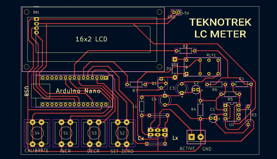
A professionally designed single-layer PCB created with KiCad ensures clean routing and minimizes interference. It includes detailed silkscreen labels for easy assembly and debugging.
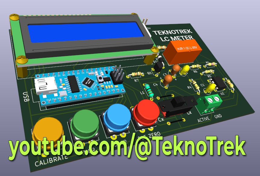
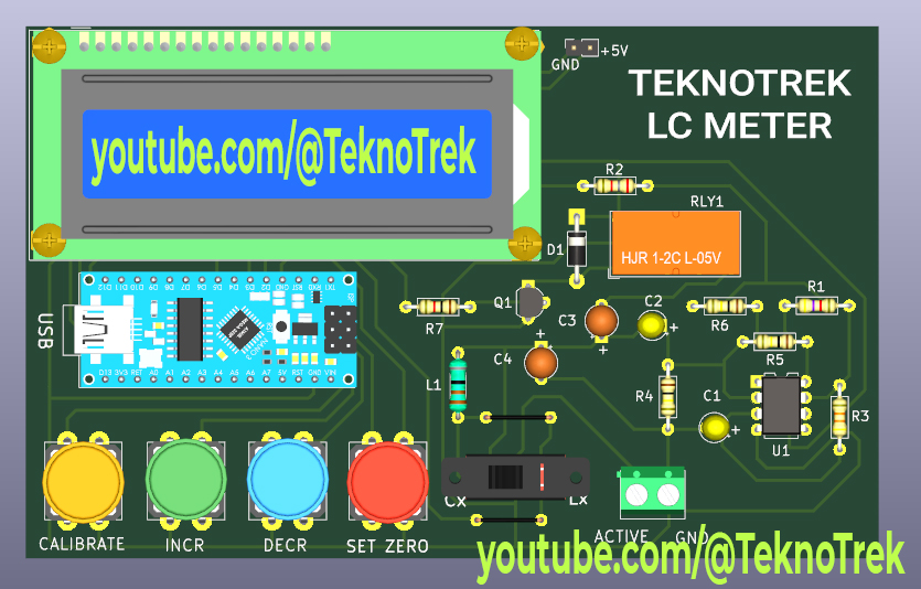
A realistic 3D representation of the completed PCB with components mounted, offering a clear view of the final product and component placement.
The Arduino Nano is programmed with custom firmware to calculate inductance and capacitance values. Measurements are displayed on a 16x2 LCD in real time.
The project includes functionality for calibration, zeroing, and easy measurement. Buttons on the PCB allow users to fine-tune settings for accurate results.
- Precise Measurements: Measure a wide range of inductance and capacitance values.
- User-Friendly Interface: Includes a 16x2 LCD display for real-time measurement results and intuitive feedback.
- Adjustable Calibration: Easily calibrate the device for accurate readings using the on-board calibration buttons.
- Compact and Portable: The design is compact, making it easy to use in different workspaces or carry for fieldwork.
Download the provided Gerber files and manufacture the PCB, or use the KiCad design to etch your own board.
Place and solder all components as per the silkscreen labels on the PCB.
Use the Arduino IDE to upload the provided sketch to your Arduino Nano. Ensure all libraries are correctly installed.
Connect the LC Meter to a 5V power source via USB or the provided input terminals. Calibrate the device using the calibration and zero buttons for precise results.
Connect your inductors or capacitors to the respective terminals (Lx or Cx) and observe the measurement results on the LCD.
You can watch the full build process of this DIY LC Meter on my YouTube channel Teknotrek. Click the link below to see how the circuit is assembled, soldered, and tested:
- Circuit schematic
- PCB design files (KiCad)
- 3D PCB model
- Arduino firmware
- Documentation with detailed assembly and usage instructions
All project files, including schematics, PCB designs, 3D models, and source code, are available on GitHub.
Check out the project here: Teknotrek
This project is perfect for anyone interested in electronics, DIY tools, or Arduino projects. Whether you are a beginner or an experienced maker,this LC Meter provides a hands-on learning experience and a functional tool for your electronics toolkit!


